| Part Code: |
Identifier: |
Description: |
| Product type: |
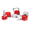
GNExH1 |
Heat Detector |
| Element guard:[g] |
N
G |
No guard
With guard |
| Temperature code:[t] |
01
02
03
04
05
06
07
08
09
10
11
12 |
140°F / 60°C
160°F / 71°C
190°F / 88°C
210°F / 99°C
225°F / 107°C
275°F / 135°C
325°F / 163°C
360°F / 182°C
450°F / 232°C
500°F / 260°C
600°F / 316°C
725°F / 385°C |
| Cable entries:[e] |
A
B
C
D
Note:
E
F
G |
2 x M20x1.5mm
2 × 1/2" NPT – adaptors
2 × 3/4" NPT – adaptors
2 x M25x1.5mm – adaptors
Options A, B, C & D reduced to 1 entry for
Product version R with LED option L or C.
1 × 1/2" NPT – adaptor, 1 x M20x1.5mm
1 × 3/4" NPT – adaptor, 1 x M20x1.5mm
1 x M25x1.5mm – adaptor, 1 x M20x1.5mm |
| Stopping plug/adaptor material: [m] |
B
N
S |
Brass
Nickel Plated
Stainless Steel |
| Equipment tag: [s] |
1
2
3
6
7 |
No Duty label, no Equip. tag
Duty label
Duty label + Equip. tag
Equip. tag only
Special label requirement |
| Product version: [v] |
E
H
I
R
Note: |
Zone 1/21, Class I/II Div 2
High temp Zone 1/21, Class I/II Div 2
Zone 0/21, Class I/II Div 1
Zone 0/21, Class I/II Div 1
with EOL and/or series devices
Versions E, H, I & R: IECEx, ATEX, UL, cUL, ULC |
| Product option: [o] |
1
W
X |
Standard product
Alternate EOL & series wiring
Custom configuration – contact E2S |
| Enclosure colour: [x] |
R
S |
Red
Special – contact E2S for alternative enclosure colours |
| LED indicator: [u]: |
N
L
C
Note: |
No LED
LED with 1.5K ballast resistor
LED without ballast resistor <20mA
LED only available with Product version R |
For product version R only suffix the part code with required EOL and series devices as follows for factory installation.
See the GNExH1-IR installation manuals for resistance, wattage and diode specifications: |
E.O.L.Module: [e]
optional |
ExxxR
ED1
ExxxZ |
Resistor value in Ohms e.g. E470R = 470 Ohm
Diode IN5401 = ED1
Zener diode e.g. E5V1Z = 5.1V |
Series Module: [s]
optional |
SxxxR
SD1
SxxxZ |
Resistor value in Ohms e.g. S1K5R = 1.5K Ohm
Diode IN5401 = SD1
Zener diode e.g. S5V1Z = 5.1V |


.png)